 | |||||
The pin-fed waveguide pyramidal horn antenna is a common antenna that is widely used in systems which require a high efficiency directive antenna. This type of antenna is built by means of flaring the front of an open ended waveguide, this flare takes on the shaped of a horn. The horn shape helps to transition the waveguide mode into a free-space mode, directing energy into a high gain beam. Horn antennas are widely used as feeder antennas. One main application for these types of feeder antennas is to feed a parabolic dish increasing the gain of the total system, of as a directive element for large phased arrays.
Pin-fed pyramidal horns are commonly used as a universal standard for calibration and gain measurements, these types of horns are often referred to as standard gain horns.
Equations for determining the parameters for building this type of antenna are found at the end of this article.

Pin-Fed Pyramidal Horn Parameters
A well designed pyramidal horn antenna can have a peak gain ranging between 9 and 18dBi, with some horns having as much as 25dBi of gain. The gain of horn antennas often increases as the frequency of operation is increased, this is due to the electrical length of the horn increasing as the frequency is increased. Horns are considered to have a directional patterns.
Horn antennas are often fed using a coax feed line with a 


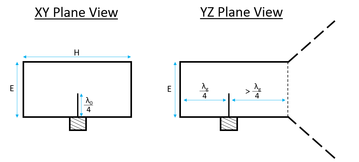
Waveguide Pin Feed Dimensions
The radiation pattern of a horn antenna depends on the angle 


Rotate Image by clicking on the image and moving the mouse
The bandwidth of a horn antenna is limited both by how the feed is designed and by the frequency range of the waveguide selected. Each and every waveguide has a specific cutoff frequency. If the feed is designed properly, the standard pin-fed pyramidal horn can works well over a sufficient bandwidth (typically greater than 15% bandwidth).
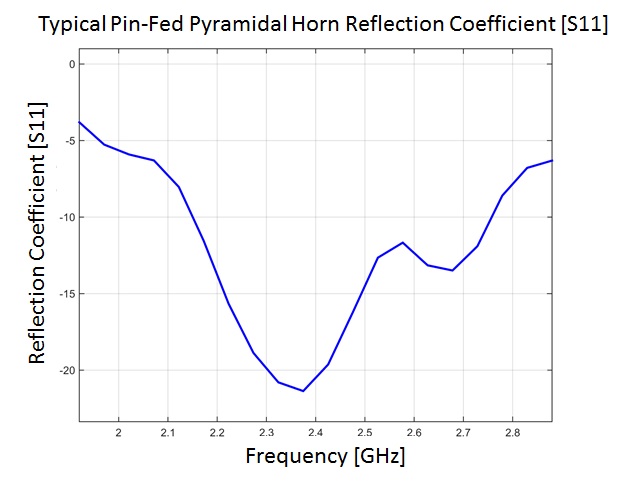
Typical Pin-Fed Waveguide Pyramidal Horn Match
The natural input impedance of a waveguide is not easy to perfectly match to 50 Ohms across wide-band operation. The reason for the imperfect match is due to the
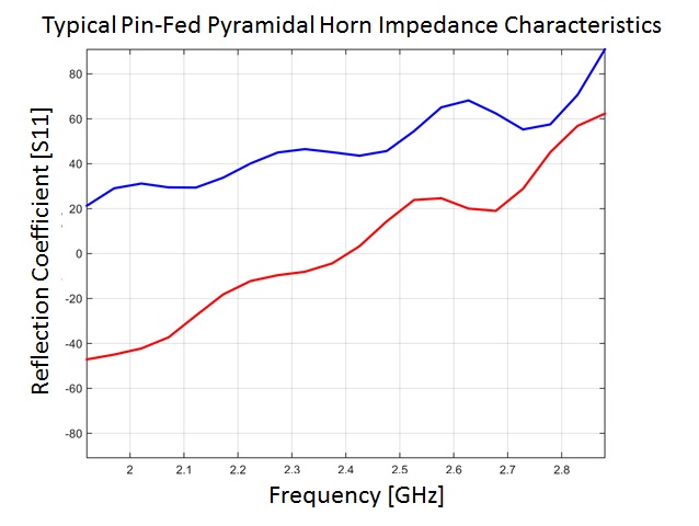
Typical Pin-Fed Pyramidal Horn Impedance Characteristics
The cutoff frequency of the waveguide selected should be less than the operating frequency of the antenna. Once a waveguide is selected the equations below can be used to design the final pin-fed pyramidal horn.
General Facts:
- Larger Waveguide = Lower Frequency
- Longer Flair = More Gain
- Bandwidth Limited by Waveguide
- Reflection Coefficient is Generally Low
Design Guidelines:
- Waveguide dimensions
- To Increase Frequency:
- Decrease waveguide width & length
- Increase Gain:
- Increase the size of aperture
&
- Increase the size of aperture


Equations and descriptions for determining the waveguide and pyramidal parameters:
See the Horn dimensions calculator to calculate these values.
RF waves can propagate in many different ways within a waveguide (often referred to as modes). For a pyramidal horn the dominant mode of the transverse electromagnetic wave is used in the rectangular waveguide. This is the 
When building a waveguide make sure that the wave guide is the right size to work well (or at all) in the required frequency range:

Maximum frequency which this waveguide should be used 
Minimum frequency which this waveguide should be used 
Height of waveguide 
Now it is possible to determine the
^2} }")
Now the size of the waveguide is known, the cutoff frequency, and the guided wavelength is known. These are all the parameters needed to make and feed the waveguide. Now it is possible to try and design a horn with optimal dimensions.
Now lets determine how much the horn should be flared. Most often it is optimal to optimize for a needed gain, in other words what is the smallest size the horn can be for a specific gain. To optimize the horn for size while achieving maximum gain the parameters 


To fully optimize the above parameters 
^2 (2 \chi - 1)= \left ( \frac{G_0}{2\pi} \sqrt{ \frac{3}{2\pi} } \frac{1}{ \sqrt{ \chi} } - \frac{a}{ \lambda } \right )^2 \left ( \frac{ G_0^2}{6 \pi^3} - \frac{1}{ \chi} - 1 \right )")
However, this equation must be solved iteratively; for a non-perfectly optimal solution, or for a starting point for the above equation the following formula can be used to solve for

Once

 \lambda")


![p_E = (b_1 - b) \left [ \left ( \frac{ \rho_e }{b_1} \right )^2 - \frac{1}{4} \right ]^{1/2}](http://s0.wp.com/latex.php?latex=p_E+%3D+%28b_1+-+b%29+%5Cleft+%5B+%5Cleft+%28+%5Cfrac%7B+%5Crho_e+%7D%7Bb_1%7D+%5Cright+%29%5E2+-+%5Cfrac%7B1%7D%7B4%7D+%5Cright+%5D%5E%7B1%2F2%7D+&bg=ffffff&fg=000000&s=1 "p_E = (b_1 - b) \left [ \left ( \frac{ \rho_e }{b_1} \right )^2 - \frac{1}{4} \right ]^{1/2}")
![p_H = (a_1 - a) \left [ \left ( \frac{ \rho_h }{a_1} \right )^2 - \frac{1}{4} \right ]^{1/2}](http://s0.wp.com/latex.php?latex=p_H+%3D+%28a_1+-+a%29+%5Cleft+%5B+%5Cleft+%28+%5Cfrac%7B+%5Crho_h+%7D%7Ba_1%7D+%5Cright+%29%5E2+-+%5Cfrac%7B1%7D%7B4%7D+%5Cright+%5D%5E%7B1%2F2%7D+&bg=ffffff&fg=000000&s=1 "p_H = (a_1 - a) \left [ \left ( \frac{ \rho_h }{a_1} \right )^2 - \frac{1}{4} \right ]^{1/2}")
With these parameters it is now possible to build the antenna, as well as back solve to verify the gain:
where 
