(Normal to Dipole) | |||||
The dipole antenna is the basis of many different antennas. The standard dipole antenna measures 1/2 wavelength total, with each side of the dipole maintaining a length of 1/4 of a wavelength. Each side of the antenna is fed 180° out of phase from the other side of the antenna.
The standard dipole has a “doughnut” shaped pattern (click to rotate 3D image below) which is linearly polarized along the length of the antenna. The peak gain of this antenna is 2dB more than that of an isotropic antenna (2dBi).
Rotate Image by clicking on the image and moving the mouse
In order to obtain this pattern shape a balun should be used when feeding this antenna with an unbalanced feed line. Often this type of antenna is fed using a coax attached to a balun. If a balun is not used the pattern will “tilt” towards one side of the dipole.
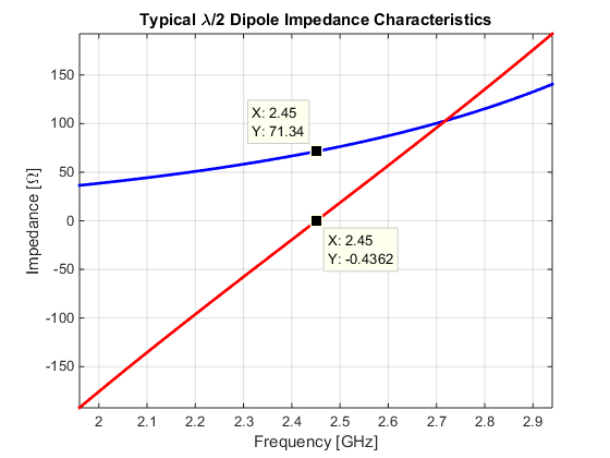
The natural input impedance of a dipole antenna is 73Ω, which is double that of a monopole antenna. Below is the standard input impedance of a thin dipole antenna centered at 2.45GHz.
A general rule is the thickness of the dipole antenna determines the bandwidth of the antenna. For a very thin antenna the bandwidth will usually be around 5% and as the thickness increases bandwidths above 20% are obtainable. For a standard dipole the thickness should be much much less than the length of the antenna. The bandwidth changes because as the dipole increases in width the slope of the imaginary impedance decreases.
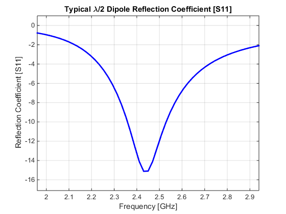
The 50Ω bandwidth this 2.45GHz thin dipole antenna is shown below. Slightly more bandwidth is obtainable when a 73Ω coax is used, this is why TV coax cable is designed to have an impedance of 75Ω.
General Facts:
- Length of λ/2
- Omni directional pattern normal to the antenna
- Linear Polarization
- 2.15dBi Gain
- Impedance 73Ω (can be fed with 50Ω with a decrease in bandwidth)
- Balun is needed to avoid pattern degridation
Design Guidelines:
- Decrease dipole length to increase the resonant frequency


