 | (elliptical) |
||||
The corner reflector antenna is one of the many types of antennas that is fundamentally based on the standard dipole antenna, with one major difference. This antenna adds a reflecting corner to the dipole creating a directional antenna. This antenna often uses a dipole as the radiating element, however a folded dipole can also be used. The dipole is mounted in front of two flat rectangular metal pieces joined (or bent) at an angle, usually between 80° and 120°.
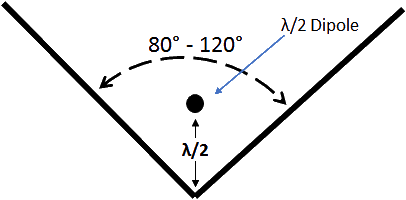
Dimensions of a traditional corner reflector
A well designed corner reflector can have a peak gain between 8-15 dBi, and as such it is considered to have a directional pattern (click to rotate 3D image below) which is linearly polarized along the length of the dipole antenna.
Rotate Image by clicking on the image and moving the mouse
It is possible to obtain higher gain by adjusting the angle of the reflector, a more acute angle will be more directional while a more obtuse angle will be less directional. It is also possible to obtain elliptical and even circular polarization by rotating the dipole in respect to the corner reflector.
The natural input impedance of a dipole antenna is 73Ω. However, when a reflector antenna is used the impedance will decrease as the size of the corner reflector is increased. The impedance will also vary with respect to the spacing between the corner and the dipole . Below is the standard input impedance of a thin dipole antenna spaced a quarter wave from the center of a large corner reflector centered at 2.45GHz.
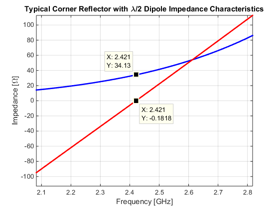
Typical impedance of corner reflector antenna
As with the dipole antenna it is possible to increase the thickness of the dipole antenna to increase the bandwidth of the corner reflector. It is important to remember that because a dipole is a balanced structure, a balun should still be when feeding the dipole.
The 50Ω bandwidth of a 2.45GHz corner reflector antenna is shown below. Slightly more bandwidth is obtainable when balun is used to transform to the proper impedance (34Ω for this particular antenna).
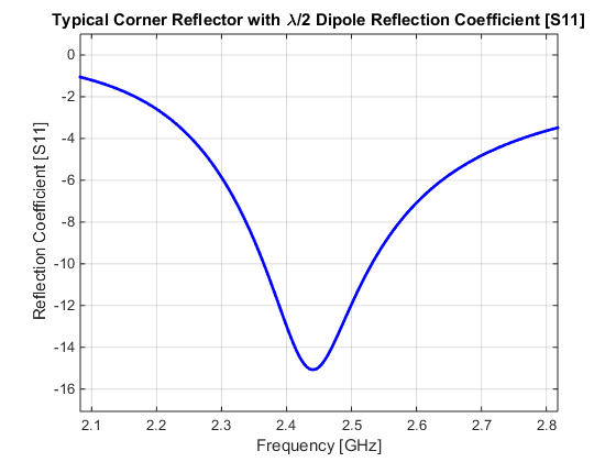
Corner Reflector Reflection Coefficient
General Facts:
- Often Fed with balanced dipole or folded dipole
- Directional pattern directed out from the acute corner of the reflector
- Linear Polarization, but Circular polarization can be obtained
- > 8dBi Gain
- Impedance 34Ω (greatly depends on distance the dipole is placed from corner)
- Balun is needed
Design Guidelines:
- Decrease dipole length to increase the resonant frequency
- Increase distance from corner to increase Impedance
- Dipole distance from corner can vary from 0.25λ to 0.75λ with little impact on performance
- Increase the reflector length and width to increase gain
- Decrease reflector angle to increase gain.